Outgassing during Siderotype Exposures
Image Resolution Degraded by Outgassing in Contact-printing Siderotypes
Chemical Theory
All the siderotype processes evolve carbon dioxide gas as a product of theirprimary photochemical reactions.
e.g. UV light + 2Fe(C2O4)33- → 2Fe(C2O4)22- + 2CO2↑ + (C2O4)2-
This applies to ferric oxalate, ammonium ferric oxalate, and ammonium ferric citrate sensitizers, and to printout or development processes, platinum or palladium, and all the others: cyanotype, chrysotype, kallitype, Van Dyke, argyrotype, etc. It will also apply to the Chibatype process for hardening pigmented colloids, which uses ammonium ferric citrate sensitiser, and to the use of diazidostilbenes to photoharden pigmented colloids, where the photolysis evolves nitrogen gas. Although salted paper printing in theory evolves chlorine gas, this will usually be speedily ‘scavenged’ by reaction with other organic components, e.g. citrate.
So this is a widespread issue for alternative processes. It will not apply to dichromated colloids, or development silver processes, where there is no gas evolution. The crucial, and previously unasked question is this: How much CO2 is formed in practice, and is it enough to matter?
Here follows a calculation for a sensitized coating such as is used for platino-palladiotype, new cyanotype or argyrotype. It assumes total conversion to photoproducts - i.e. the absolute Dmax: a "worst case”scenario.
The specific coating volume is ~25 cc/square meter, using a solution ~0.7molar in Fe(III) sensitizer, which will release an equimolar amount of CO2.
So full exposure releases 0.025 x 0.7 = 0.0175 moles of CO2/m2
Volume of this gas @ STP = 0.0175 x 22400 = 392 cc of CO2/m2
E.g. an A4 print would evolve a maximum volume of 392/16 = 25 cc of CO2
'Layer thickness' of this gas @ STP = 392 x 10-4 cm = 0.0392 cm = 0.4 mm
At Standard Temperature and Pressure (STP) the maximum CO2 gas so evolved would be equivalent to a layer of thickness ca. 0.4 mm.
In practice, the CO2 evolved will be less than this maximum, because an average picture is, say, 3 exposure stops down (1/8) on Dmax: generating CO2 thickness proportionally as ca. 0.05 mm. This will probably not actually make a uniform layer but tend to localise into bubbles, which will be locally thicker, possibly by a large factor (10x?). So we end up with the possibility of local gaps of ca. 0.1-0.5 mm.
Light Source Geometry and Image Acutance in Contact Printing
If gaps are formed between negative and sensitized surface, they may be wide enough to blur the acutance or resolution of the image, to an extent that depends on the geometry of the light source. The blur is the width of the penumbra (fuzzy zone) between light and full shadow at any edge with in the image, and depends on the ratio of size to distance of the light source. If the largest linear dimension of the light source is w, and its distance from the print is d, then w/d is the aspect value of the light source. By the geometry of similar triangles: blur = gap x aspect value
| Light Source | Aspect value w/d | Blur in mm |
| (for gap = 0.1-0.5 mm) | ||
| Sun | 0.01 | 0.001-0.005 |
| NuArc 2125 | 0.1 | 0.01-0.05 |
| 'Light bed' or open sky |
4 | 0.4-2.0 |
The human eye at its near-point (ca. 250 mm) can resolve ~0.1 mm, but 0.25 mm is taken to be acceptably 'sharp' in calculating the 'depth of field' of lenses. Take 0.3 mm of blur as the onset of a 'fuzzy' or 'soft' image. So the CO2 is only likely to cause a visible problem with 'light bed' sources, and blurring will be most conspicuous where the local contrast is high.
Properties of the Printing Paper
The $64,000 question is: Where will this CO2 go? Some or all of this CO2 may be absorbed into the voids of the printing paper itself, which constitute ca. 50% of its actual volume (although not all this may be accessible even to a gas). For instance, a 240 g/m2 paper with a density of ca. 0.75 g/cc has a total volume of ca. 320 cc/m2, and therefore a void volume of 160 cc/m2. If the maximum volume of gas evolved, 392 cc/m2, were compressed into this void, already full of air at one atmosphere, the pressure would have to increase to 3.5 atmospheres, which seems physically impossible in a contact printing frame. However, for an ‘average’ emitted gas volume of 392/8 = 48 cc/m2, the pressure would increase to 1.3 atmospheres, which may be physically possible. It’s also conceivable that high humidity may assist the absorption of CO2, owing to the equilibria:
CO2 + H2O ⇌ H2CO3 ⇌ H+ + HCO3- ⇌ 2H+ + CO32-
It is important to the print quality that this gas should find a pathway to diffuse out from the sensitized surface, through the back of the paper, to avoid the possibility of forming bubbles trapped between negative and sensitized surface. The permeability of the printing paper should allow passage of the CO2 gas through to its verso, and it is essential that the sensitized paper sheet should be backed in the contact printing frame with a felt blanket, or other porous sheet material permeable to gases, which will absorb the CO2 under pressure.
Experimental Observations
This loss of sharpness will only become obvious in rather extreme images like my step tablet tests (below) printed with a solarium, but not in most pictorial prints. It was only when I backed some of my step-test printing papers with impervious plastic film like Mylar that the loss of acutance became glaringly apparent (to my shame, I had recommended the plastic sheet - because I was worried about RH control, loss of water, and the effect of the slit in a hinged-back printing frame). I noticed bad blurring of some numbers on the Stouffers when these are exposed to a bank of UVA fluorescent tubes, but not when they are exposed to a small HID lamp in the NuArc in the same contact frame (without vacuum).
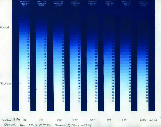
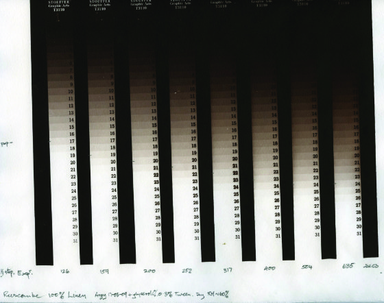
This was true for platinotype, palladiotype, new chrysotype, argyrotype, and new cyanotype. The effect can be seen in the attached .jpgs of a new cyanotype and an argyrotype on Herschel paper. Note the blobby numbers in the middle region. I originally just put this down to a faulty or inadequate pressure frame, but now I know better. The "soft spots" must be due to CO2 bubbles between negative and paper - in retrospect, it's obvious! The figures derived above suggest that this effect is just on the edge of observability, and most practitioners will deny that they have ever seen it. But when one thinks of the pains that some photographers go to, with 10x8 inch and other large format camera negatives etc., for achieving that special high-resolution 'look', it should be worthwhile to bear the CO2 in mind, and not allow it the slightest opportunity to degrade the image, however unobviously.
Remedies and Precautions
If the printing paper in the contact frame is backed with a conservation grade felt blanket (the sort used by papermakers) instead of impervious plastic, then I find that the problem is cured: there is no blurring of cyanotype or palladiotype even with heavy exposure to a bank of UVA fluorescent tubes.
In the vacuum easel of the NuArc 2125 it may seem a bit counterintuitive pumping down to vacuum under a felt blanket, but it works. Without the blanket, one can sometimes actually see bubbles of gas generated under the rubber backing sheet during the exposure!
Obviously, papers will differ, and for some papers their two surfaces may differ in permeability.
The permeability to gases could be a paper characteristic previously unrecognised as important for image quality in contact printing all siderotypes with 'light bed' sources.
E.g. gelatine sizing may block the pores. Parchmentized paper (e.g.vellum) will have lower porosity. Plastic substrates such as 'Yupo' will be completely impermeable. Papers adhered to aluminium plates will be impervious.
To summarise: the following factors will tend to influence the resolution by increasing or decreasing the effect of trapped CO2 gas (roughly in descending order of importance):
| Factors degrading resolution | Remedying loss of resolution |
| A diffuse light bed (solarium) | Nearly a point source (sun or NuArc) |
| Impervious print backing | Permeable print backing sheet |
| Exposed image borders | Masked image borders |
| Dark images | High key or light images |
| Thin glazed papers | Thick but permeable papers |
| Surface ('tub') sized paper with film-forming colloid Parchmentized papers (vellum) |
Internal ('engine') sized paper (AKD) |
As far as I know, in 172 years of iron-based printing, no-one has ever mentioned anything about the issue of the CO2 gas, and where it goes!…but we have been making our small contribution to Global Warming...
back to top